Arcade Machine
This project was driven by my desire to refresh my skills at Computer Assisted Design (CAD) and my desire for an arcade machine. I had used SolidWorks extensively during my university degree, and NX, formerly Unigraphics, during my internship at Holden. For this project I decided to use Autodesk Fusion for the modelling largely because they had a free license for hobbyist and non-commercial use, but the tool itself has some interesting features and was cloud native for synchronising data across computers and easy collaboration.
Arcade Hardware
To begin the project, I began searching images of Arcade Machines for inspiration and to get a feel for the general layout and geometry. I had decided early I wanted a 4-PLayer Arcade Machine. I sourced and procured the arcade control equipment that I needed. I picked these up from OzStick, an Australian arcade supplier.
The bill of materials for the arcade parts is as follows:
| Part | Quantity |
|---|---|
| I-PAC4 Keyboard Encoder | 1 |
| Wiring Kit | 6 |
| Sanwa Joystick (Red) | 1 |
| Sanwa Joystick (Green) | 1 |
| Sanwa Joystick (Blue) | 1 |
| Sanwa Joystick (Black) | 1 |
| Sanwa OBSF-30 Pushbutton (Red) | 8 |
| Sanwa OBSF-30 Pushbutton (Green) | 8 |
| Sanwa OBSF-30 Pushbutton (Blue) | 8 |
| Sanwa OBSF-30 Pushbutton (Black) | 8 |
| Coin Button | 4 |
| Dimpletop Pushbutton (Player 1 - White) | 1 |
| Dimpletop Pushbutton (Player 2 - White) | 1 |
| Dimpletop Pushbutton (Player 3 - White) | 1 |
| Dimpletop Pushbutton (Player 4 - White) | 1 |
Tip
The wiring kits are a massive time saver. Pre-crimped wires to connect to the microswitch and terminate in the I-PAC4 Keyboard Encoder via screw terminal. I highly recommend.
Computer Aided Design
With the parts sourced, I began modelling them in Autodesk Fusion using digital calipers. This ensured that my assembly for the arcade control box will accurately consider the dimensions of the fitted controls. This step is critically important to ensure the modelled layout of the controls are accurate with enough space to accommodate 4-players comfortably.
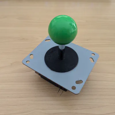
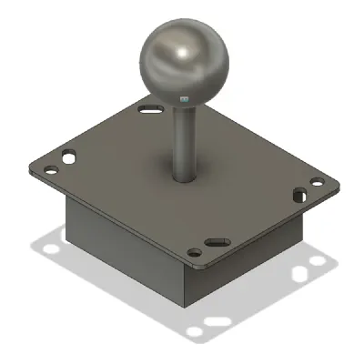
Sanwa joystick vs modelled Sanwa joystick
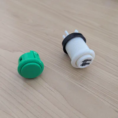
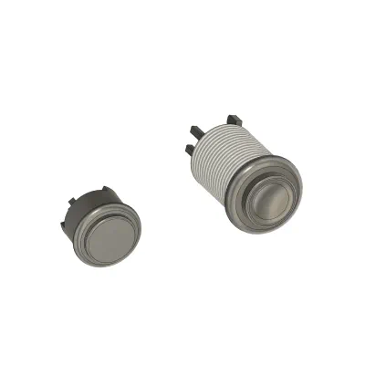
Push buttons vs modelled push buttons
With the arcade control parts modelled, next I focused on the layout scheme for the controls and how players 1 through 4 would be laid out on the playing surface. Slagcoin is an excellent resource for arcade control layouts. Scrolling through the list of standard layouts I decided on the Sega layout as it had a natural contour of the push button layout that aligned ergonomically with the hand. I then proceeded to sketch an outline of the playing surface in Autodesk Fusion and arranged the four players using the Sega layout. The playing surface will be manufactured from some 4mm thick clear acrylic sheet.
Playing Surface sketch with Sega control layout
With the playing surface layout established, I proceeded to model the control box, using the modelled playing surface to orient the holes, cutouts and overall geometry required to accommodate the joysticks and push buttons.
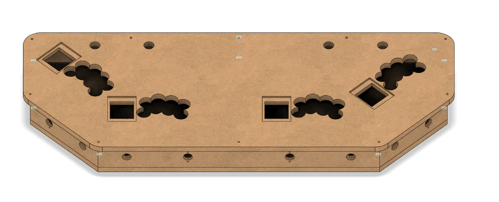
Playing Surface sketch with Sega control layout
With the control box modelled, I can bring together the assembly in Autodesk Fusion with all the controls fitted, materials textures applied to the model components and a decal applied to the playing surface.
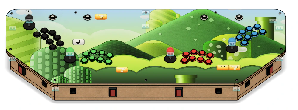
Control Box assembly
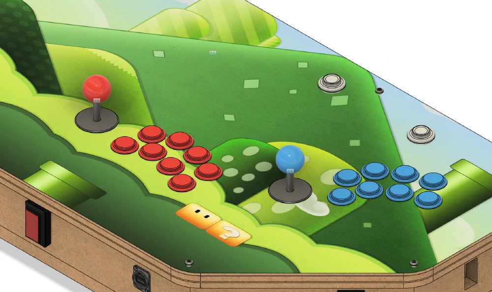
Zoomed view of the Control Box assembly
Having established the control box for the arcade machine, I moved onto modelling the rest of the cabinet. I used the control box as a reference to scale the rest of the arcade machine and used online images of other arcade machines as a reference to establish the geometry of the cabinet.
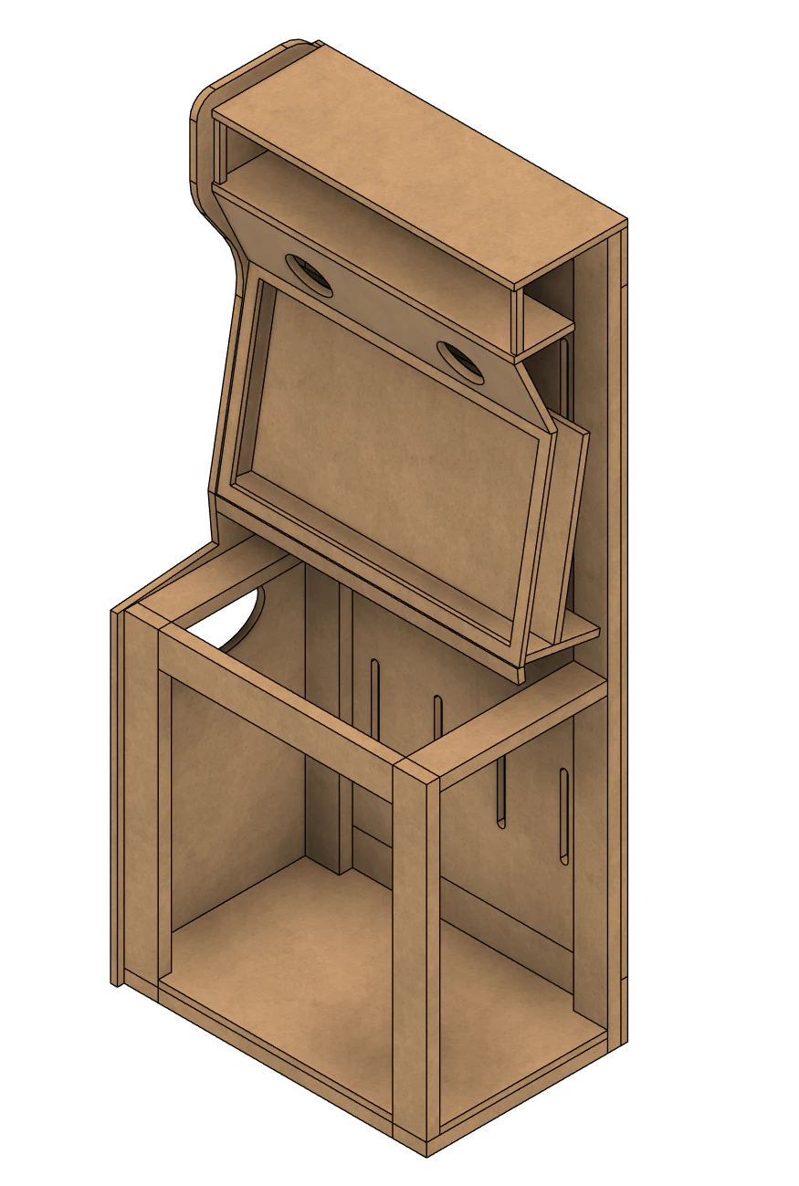
Arcade cabinet frame
With the arcade machine frame and panels established, I brought together the full assembly with speakers, monitor and the Control Box.
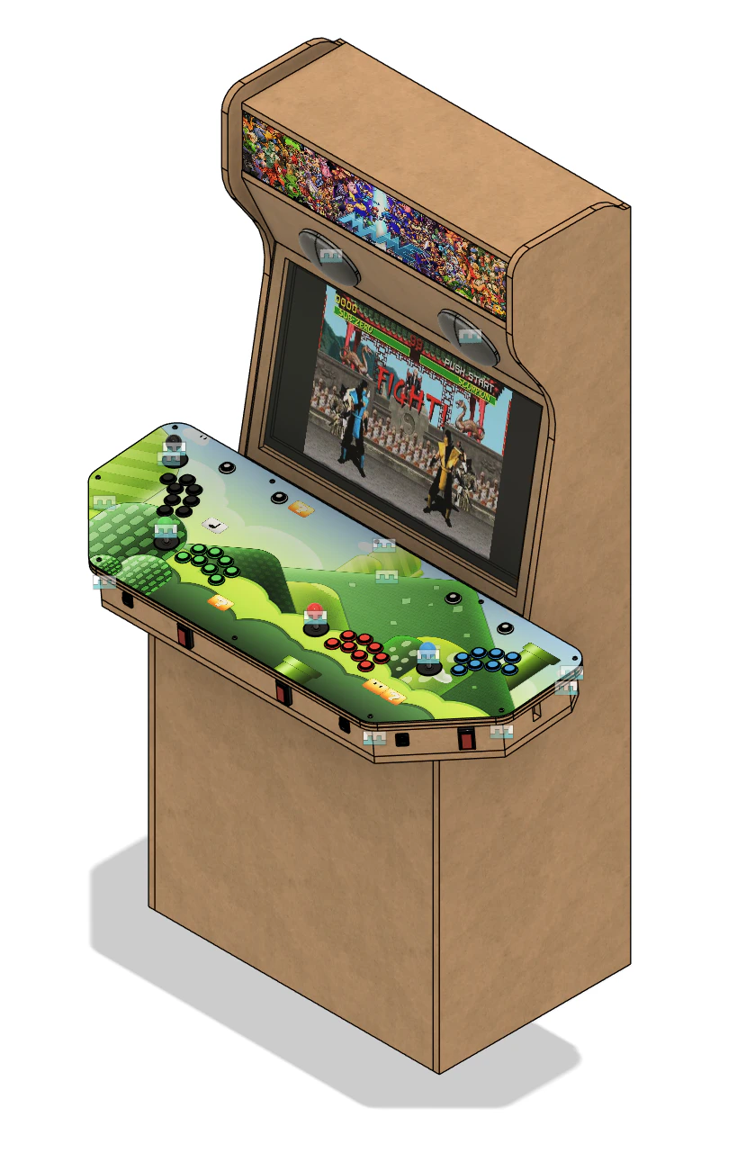
Arcade cabinet assembly
Manufacturing
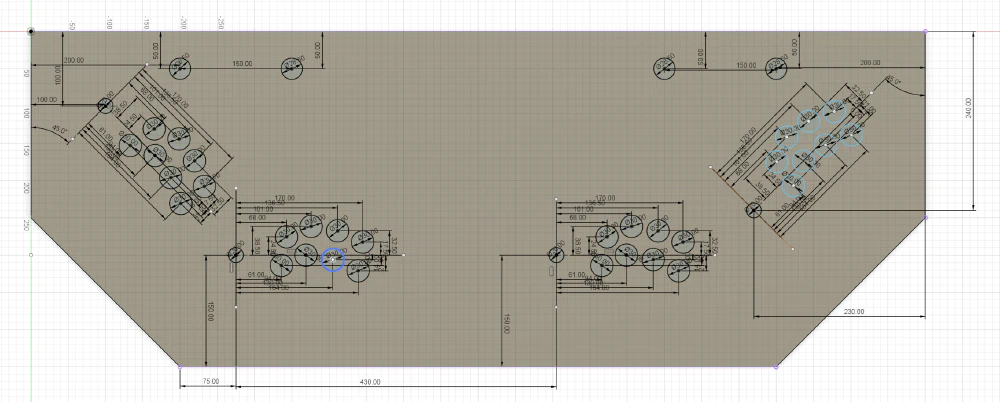
With the arcade machine modelled in Autodesk Fusion, it was onto manufacturing. I created technical drawings for each of the parts of the arcade machine assembly.
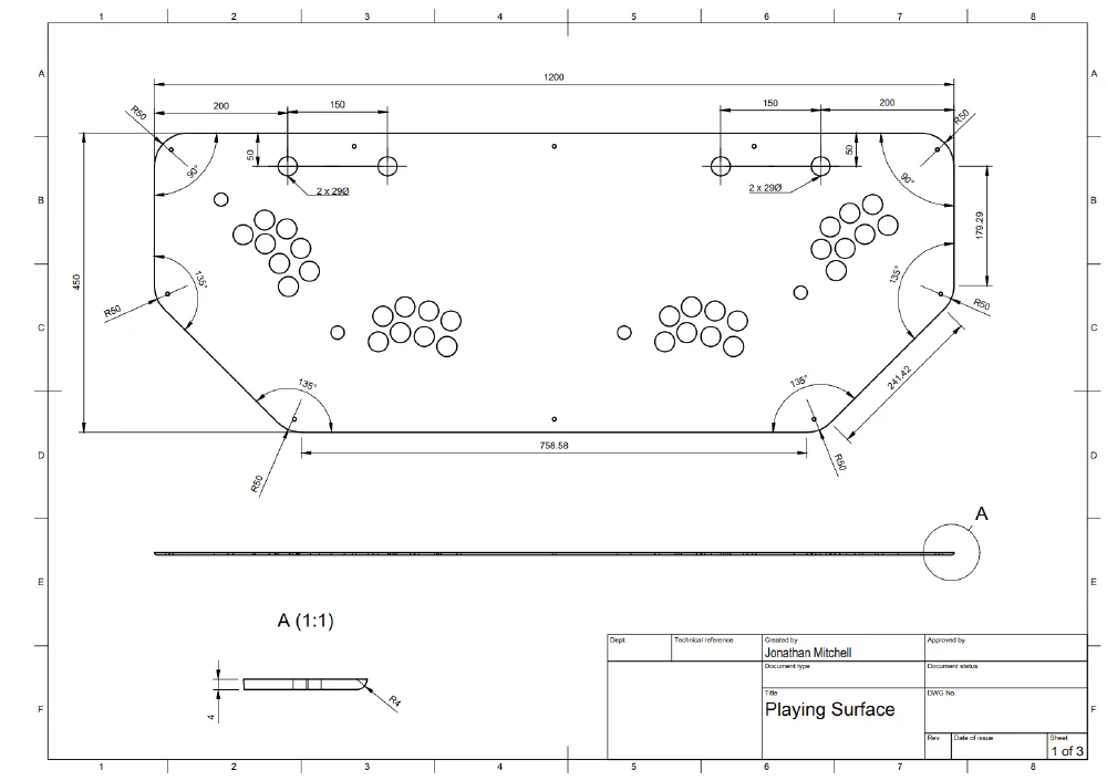
Playing Surface drawing 1/3
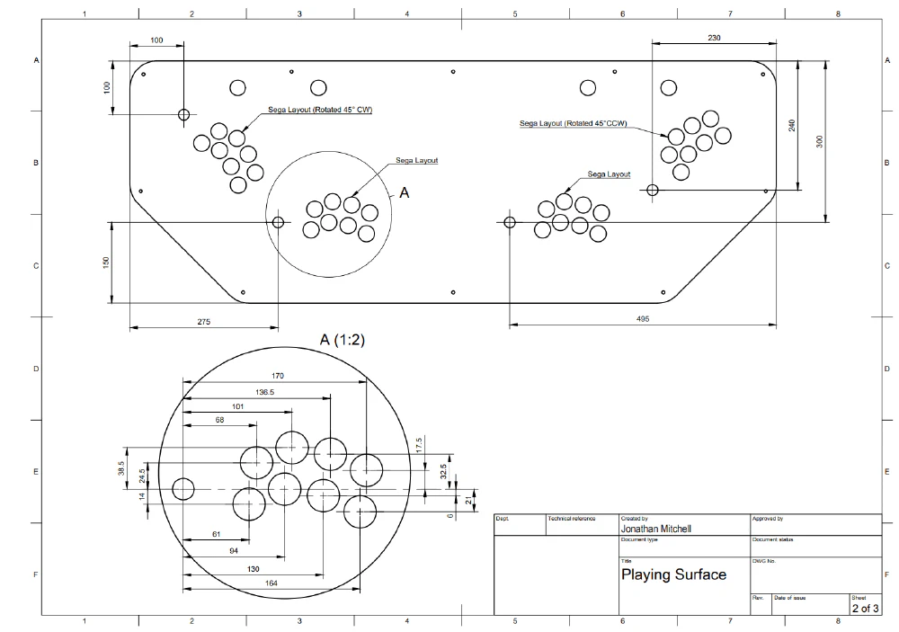
Playing Surface drawing 2/3
At the time I made the arcade machine I was living in a two bedroom apartment in Sydney and didn’t have the space or tools to manufacture the arcade machine myself. I reached out to local cabinet makers and light fabrication shops that had a CNC router to get quotes on producing the parts. Unfortunately I couldn’t find a supplier willing to do the work for a price I was happy to pay. Instead I decided to manufacture the control box myself using the tools I did have available. However, I was not able to manufacture the playing surface myself. Luckily I did manage to find a fabrication shop that could laser cut the playing surface from acrylic sheet using my 3D model and technical drawings for a fair price.
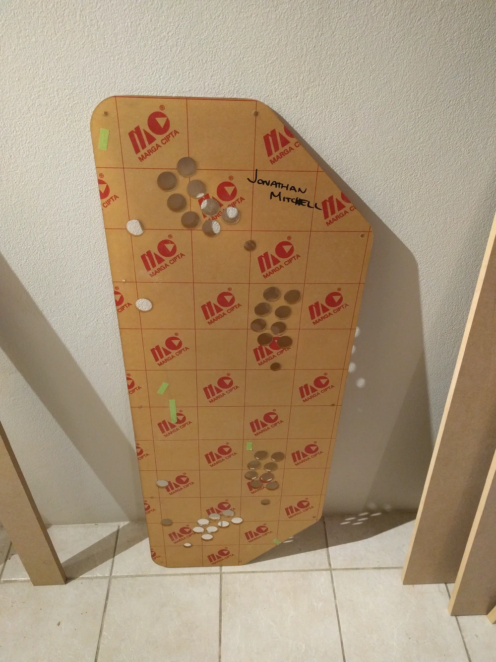
Playing Surface
Using the laser cut acrylic playing surface as a stencil I cut out the bulk shape and holes required to accommodate the arcade controls. I used a jigsaw, router and drill to shape the Control Box as per the design in Autodesk Fusion.
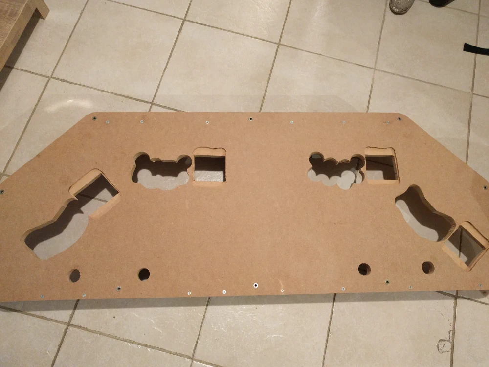
Assembled Control Box with cutouts for arcade controls
I then applied a primer coat and painted it black. Finally, I fitted the acrylic playing surface using screws and applied a Super Mario decal to the playing surface.
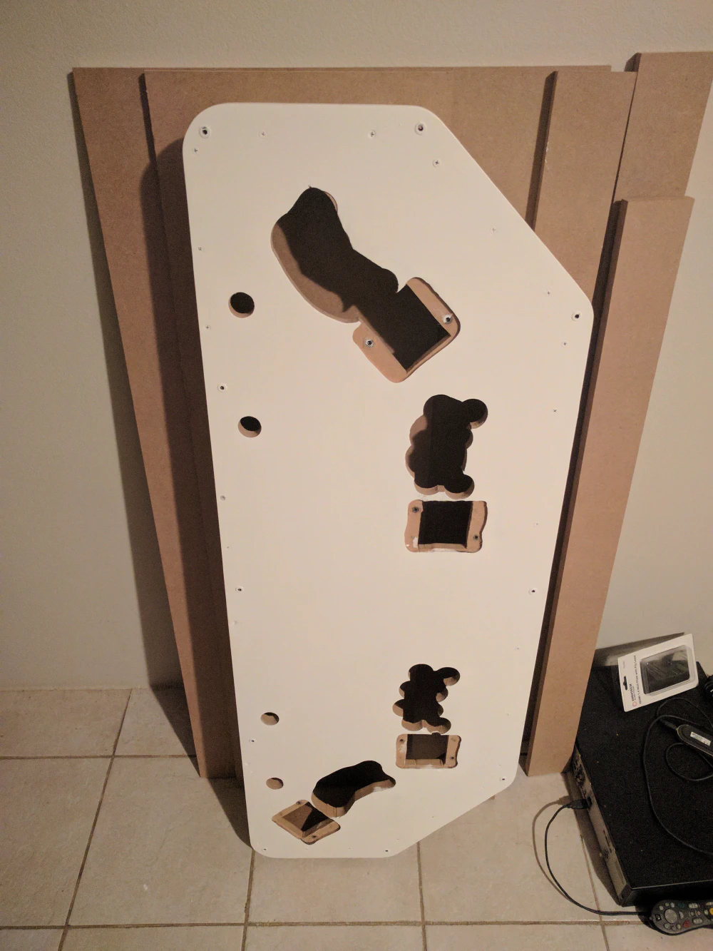
Primer coat on Control Box
With the Control Box manufactured, I moved onto installing the arcade controls, electronics and wiring it up.
The bill of materials for the electronics in the control box is as follows:
| Part | Quantity |
|---|---|
| Raspberry Pi | 1 |
| Power Supply | 1 |
| IEC 14 Power Socket Chassis | 1 |
| Solder Finished Prototype PCB | 2 |
| 40mm Fan | 2 |
Using the wiring kits procured at the arcade supply store, I fitted the arcade controls and wired them to the IPAC-4 keyboard encoder. The power supply provided the voltages required for the fans and Raspberry Pi. The IPAC-4 connected directly via USB to the Rapsberry Pi.
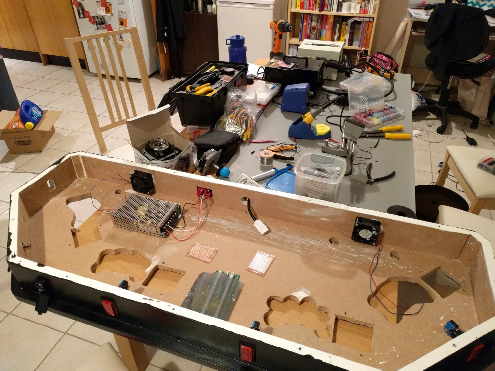
Control Box with Power Supply and Fans fitted
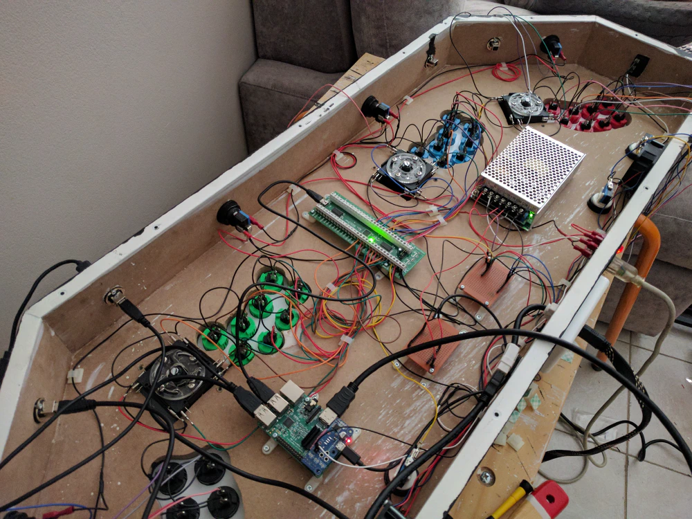
Control Box with controls fitted and half wired
Testing control input for Players 1 and 2
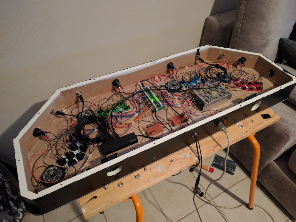
Control Box with wiring completed
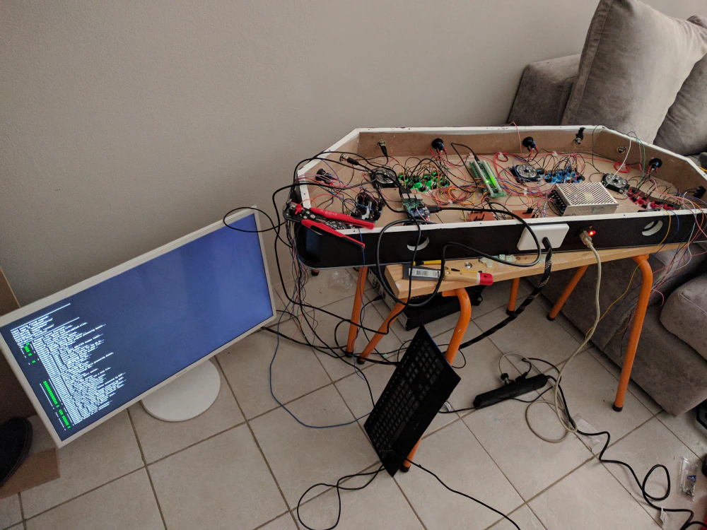
Now that the controls box had all the controls fitted and wired, it was time to configure MAME and the IPAC-4 Keyboard Encoder.
Finished Project
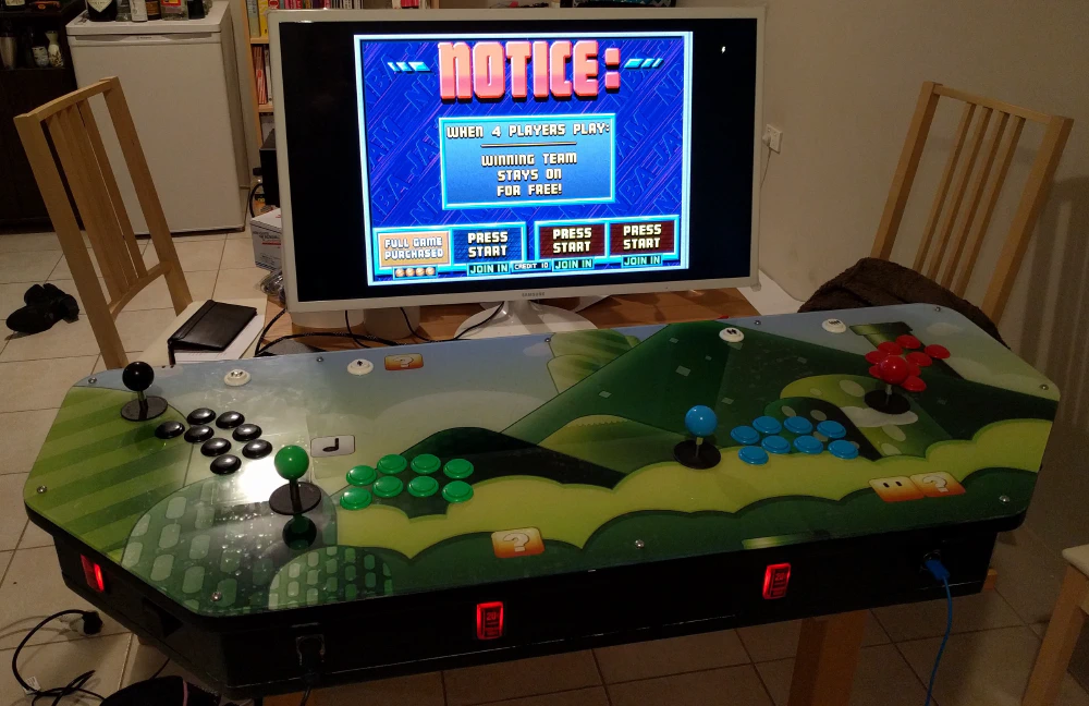
MAME running on the Raspberry Pi with the finished arcade control box
Success! I had the 4-Player Control Box finished and working with MAME on a Raspberry Pi.
Sadly I had to stop here due to a lack of space in my apartment at the time and the inability to find a manufacturer for the rest of the cabinet since I lacked the tools and space to build it myself.
I have yet to make the cabinet to complete the arcade machine. I intend to revisit the project in the future and redesign the arcade machine to incorporate lessons learnt. For example, players 3 and 4 only need at most 4 buttons as there are no arcade games that support more than 4 buttons for 4 player games.
This was a very engaging project that gave me the motivating focus to refresh my CAD skills and learn Autodesk Fusion. I found Autodesk Fusion very intuitive, comparable with the other CAD tools I’ve used in the past. I also learnt a lot in building the arcade control box itself. For example I learnt its very hard to cut straight edges with a jigsaw, but I got the job done with the tools I had available.